
Understanding Remote Frequencies
There are many frequency bands available for industrial remote controls. Bands are groups of frequencies that may consist of channels. There may be one channel or many channels which are typically governed by each country’s regulatory body for which the remotes will be used. Without getting too technical, below is a broad description concerning frequencies.
Different Types of Remote Control Frequencies
Most industrial remote control manufacturers try to utilize a frequency so that the equipment does not have to be licensed at the user level. They still have to be tested and meet all the requirements (usually Parts 15 in the United States) but this burden is on the manufacturers. Should a user need special units for example range or their own band, not only would the manufacturer have to meet the regulations, but the user may have to be licensed as well.
There have been some IR remotes manufactured but most are RF (radio frequency). There are pros and cons for each. IR remotes had problems with the sun “blinding” the signal path. Also dust/dirt could interfere with the signals. RF remotes have different characteristics at different frequencies.
MHz vs. GHZ
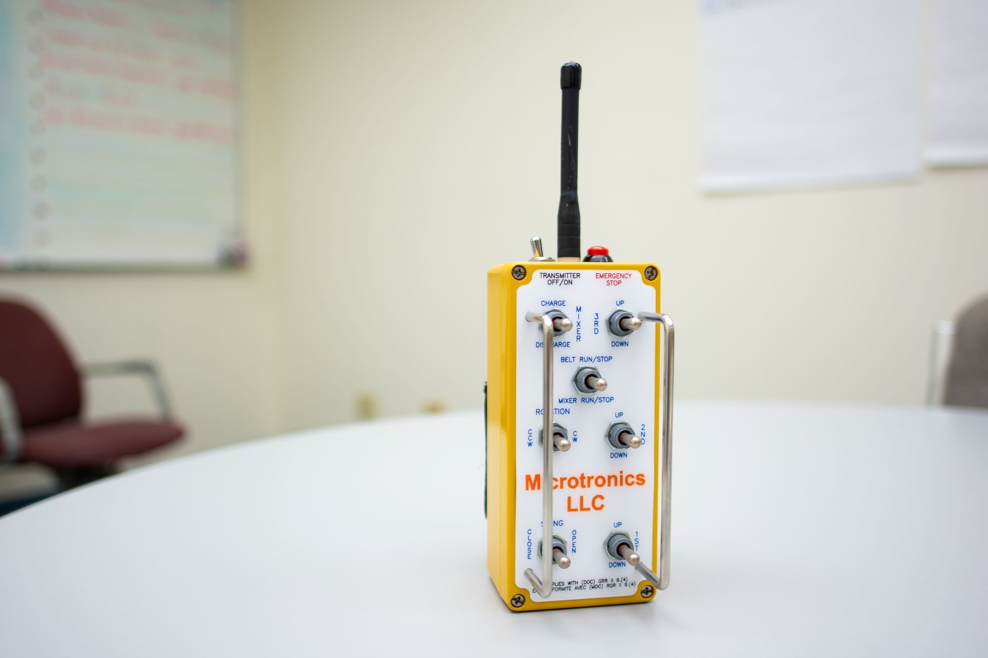
Frequency is labeled as Hertz. One Hertz is one cycle per second. MHz is MegaHertz and is one million cycles per second. GHz is GigaHertz and is one billion cycles per second. Before choosing you should be aware of where you can use particular frequencies, as some countries will have certain frequency restrictions and laws. Microtronics, LLC utilizes the 49MHz band and 2.4GHz band.
PROS & CONS of Lower Frequencies vs. Higher Frequencies
LOWER FREQUENCIES:
Lower frequencies are less expensive to manufacture. Components are less expensive. battery consumption is less for a given range, and equipment for production and/or service is less expensive.
Lower frequencies have long wavelengths and therefore have long antennas. Antennas are the matching device between the atmosphere and the electronics. It’s basically a transformer that matches the atmosphere impedance (typically 300 ohms) to the output impedance of the electronics (typically 50 ohms). The impedance of the electronics may vary so the antenna has to be tuned so this variance must be transformed to the atmospheric impedance.
The antennas will only be a partial of the actual wavelength because it would be impractical. For instance, a unit that uses 49MHz would have a wavelength a little over 6 meters.
As you can see, this would be very impractical. Therefore, antennas are cut at some percentage of the wavelength and use techniques of “coiling” the internal antenna wire, and may use “loads” (typically base loads, center loads, as well as top loads) that will simulate to desired frequency. There is typically matching circuitry to fine tune the impedance matching of the antenna.
All frequencies exhibit multipath or sometimes known as ghosting. A crude analogy I like to use for those of us that remembers the older TVs using outside antennas, is while watching a show and maybe a figure moves across the screen. Sometimes, it seemed that there was a faint figure (same as the original but very dim (ghostly)) following right behind the original.
This is caused by “Multipath”. This occurs because the signal from the transmitter (in this case the TV station) makes it to the TV antenna firstly in a straight line. A second signal may reach the TV antenna after it is reflected off an object usually made of metal. This second signal will not be as strong as the original signal and delayed in time because of the extra distance it had traveled. A TV receiver did not know the difference and it would show the “ghost” across the screen.
When an industrial remote system experiences this phenomenon, the data stream becomes “scrambled” and does not react to the data stream. Sometimes this can be made better by the operator moving around a short distance so the receiver does not experience this. Lower frequencies tend to experience this more than higher frequencies because higher frequencies have a shorter wavelength.
Please be aware, it still happens at higher frequencies it just takes less distance for the operator to move.
This phenomenon can be unintentionally caused by the location of the handheld but more so the location of the controller. A scenario that I like to refer to is again the outside TV antenna. These are usually yagi antennas. This type of antenna looks like an oversized arrowhead. There are several metal arms along the length of the antenna. These are called elements.
Only one of these elements is the “antenna” that delivers the signal to the TV. There are longer elements that are called “reflectors” while the shorter elements are known as “directors”. The reflectors will reflect signals that have “passed” the signal element while the directors direct the signals coming in to the signal element.
So what! Well if the receivers’ antenna is mounted on a piece of equipment that has a lot of metal around it, this metal may cause issues. If it happens to act like a director, then everything works great. If this surrounding metal acts as a reflector a couple of examples may be exhibited.
If it reflects the signal away from the antenna, the controller would not see and will not operate. But, if it reflects the signal to the antenna, everything works fine. Just remember: Metal to RF is like a mirror is to light. Metal usually reflects RF.
Pros:
- Less expensive componentry and circuit board design
- Less battery consumption at a given range
- Will “fill in” around objects while propagating
Cons:
- Multipath (Ghosting)
- Usually has an external antenna
- Larger components and housings
HIGHER FREQUENCIES:
Characteristics change as the frequency increases, the wavelength decreases, therefore the antennas physically get smaller and may be internal to the housing on the transmitter. This antenna may be a “tuned” piece of wire, circuit board trace, or a surface mounted “chip” antenna.
For the signal to travel the same distance, higher frequencies need more battery power. Higher frequencies do not tend to follow the curvature of the earth. An obstacle blocking the path typically blocks it continuously. Higher frequencies tend to need a more of a “line of sight” path from handheld antenna to controller antenna. The two antennas have to “see each other” without any interfering obstacles.
Typically the controller antenna needs to be placed as high as possible so the handheld antenna can “see” and connect to it. Since higher frequencies are more of a line of sight propagation, they are best to use for satellite transmissions such as communications, GPS, and etc.
Higher frequency units are more expensive to design, manufacture, and test. Circuit boards are designed with small traces and components. Everything can act like antennas and propagate emissions causing legal ramifications or they can receive extraneous signals that cause the electronics not to work. Because of this, most components become leadless and are surface mounted using highly accurate placing equipment to populate the circuit boards.
High frequencies still can have multipath situations as well. They are not as pronounced but they still exist. Also, the higher bands are becoming more congested. This causes interference that can “overwhelm” the electronics and cause the equipment to perform intermittently or stop working. Spread spectrum technology is becoming more popular as a means to keep the handheld and controller communicating.
Pros:
- Smaller components and circuitry
- Smaller and/or internal antennas
- Smaller packaging
- Technology to reduce multipath and dropouts
Cons:
- More expensive to manufacture
- More battery consumption for a given range
- Design is more critical and intense
- Cleanliness is very critical through the manufacturing process
Bottom Line
There are many more aspects that are too technical to dive into here. This post is to help the average operator understand what to look for in controller antenna installations, the importance of obstacles in the work area, and be able to hypothesize what is occuring during operation.